Rivets
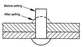
Rivets are non-threaded fasteners that are usually manufactured from steel or aluminum. They consist of a preformed head and shank, which is inserted into the material to be joined and the second head that enables the rivet to function as a fastener is formed on the free end by a variety of means known as setting. A conventional rivet before and after setting is illustrated in the figure.
|
|
|
Conventional rivet before and after setting. |
Rivets are widely used to join components in aircraft, boilers, ships and boxes and other enclosures. Rivets tend to be much cheaper to install than bolts and the process can be readily auto mated with single riveting machines capable of installing thousands of rivets an hour.
Rivets can be made from any ductile material, such as carbon steel, aluminum and brass. A variety of coatings is available to improve corrosion resistance. Care needs to be taken in the selection of material and coating in order to avoid the possibility of corrosion by galvanic action. In general, a given size rivet will be not as strong as the equivalent threaded fastener.
The two main types of rivet are tubular and blind and each type is available in a multitude of varieties. The advantage of blind rivets is that they require access to only one side of the joint. A further type of rivet with potentially many overall advantages, from the production perspective, is self— piercing rivets that do not require predrilled holes. The rivet is driven into the target materials with high force, piercing the top sheets and spreading outwards into the bottom sheet of material under the influence of an upsetting die to form the joint.
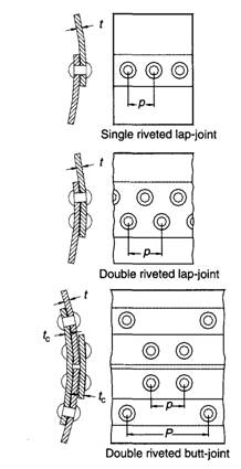
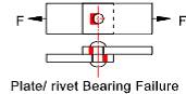
Factors in the design and specification of rivets include the size, type and material for the rivet, the type of join, and the spacing between rivets. There are two main types of riveted joint: lap— joints and butt—joints (Figure 2). In lap joints the components to be joined overlap each other, while for butt joints an additional piece of material is used to bridge the two components to be joined which are butted up against each other. Rivets can fail by shearing through one cross-section known as single shear, shearing through two cross-sections known as double shear, and crushing. Riveted plates can fail by shearing, tearing and crushing.
For many applications, the correct use of rivets is safety critical and their use is governed by construction codes. For information and data concerning joints for pressure vessels reference to the appropriate standards should be made, such as the ASME boiler code.
|
|
|
Fig. 2 Some types of riveted joints. |
Riveted joints can be designed using a simple procedure (Oberg et al., 1996) assuming that:
• the load is carried equally by the rivets;
• no combined stresses act on a rivet to cause failure;
• the shearing stress in a rivet is uniform across the cross—section;
• the load that would cause failure in single shear would have to be double to cause failure in double shear;
• the bearing stress of the rivet and plate is distributed equally over the projected area of the rivet;
• the tensile stress is uniform in the section of metal between the rivets.
The allowable stress for a rivet is generally defined in the relevant standard. For example, the
ASME boiler code lists an ultimate tensile stress for rivets of 379 MPa, ultimate shearing stress of 303 MPa and an ultimate compressive or bearing stress of 655 MPa. Design stresses are usually 20 per cent of these values, i.e. for tensile, shear and bearing stresses the design limits are 75, 60 and 131 MPa, respectively.
For a single lap joint, the safe tensile load based on shear is given by
L = n Ar τd
For a single lap joint, the safe tensile load based on compressive or bearing stress is given by
L = n Ab σc
Ab = t d
For a single lap joint, the safe tensile load based on tensile stress is given by
L = Ap σt
Where:
L is load (N),
n number of rivets,
Ar, cross-sectional area of rivet (m2),
Ab, projected bearing area of rivet (m2),
Ap cross-sectional area of plate between rivet holes (m2),
t thickness of plate (m);
d diameter of rivet (m);
τd, allowable shear stress (N/m2),
σc allowable bearing or compressive stress (N/m2),
σt allowable tensile stress (N/m2).
The efficiency of a riveted joint is given by:
η = least safe load / ultimate tensile strength of imperforated section
Rivets, however, are available as stock items from specialist manufacturers and suppliers in a much wider variety. For any given application the relevant standard should be referenced and a range of manufacturers’ products considered.
Example:
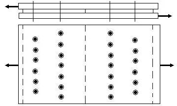
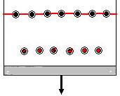
Determine the maximum safe tensile load that can be supported by 1 m section of double riveted butt joint with 15 mm thick main plates and two 8 mm thick cover plates. There are six rivets in, each of the outer rows and seven rivets in each of the inner rows. The rivets are all 20 mm in diameter. Assume that the drilled holes are 1.5 mm larger in diameter than the rivets. The value for the design limits for tensile, shear and bearing stress can be taken 75, 60 and 131 MPa, respectively.
|
|
Solution:
In analyzing a double riveted joint, it is only necessary to analyze one side due to symmetry.
The safe tensile load based on double shearing of the rivets is equal to the number of rivets times the number of shearing planes per rivet times the cross-sectional area of the rivet times the allowable shearing stress.
|
|
L = n x 2 x Ar τd
n = 6 + 7 = 13
L = 13 x 2 x (π/4) (0.02)2 x 60 x 106
= 490.1 kN
The safe tensile load based on bearing stress is given by (main plate)
|
|
L = n Ab σc
L = 13 x (0.02 x 0.015) x 131 x 106
= 510.9 kN
The cover plates have a combined thickness greater than that of the main plates, so detailed analysis need not to be considered here.
The safe tensile load based on tensile stress,
|
|

L = Ap σt
Ap = t (w – n dh) = 0.015 (1 – 6 (0.02 + 0.0015))
= 0.01307 m2
L = 0.01307 x 75 x 106
= 980.3 kN
To complete the analysis it is necessary to consider the sum of the load that would cause tearing between rivets in the inner section plus the load carried by the rivets in the outer section. The sum of the loads is used because if the joint is to fail it must fail at both sections simultaneously.
|
|
L = n Ap σc
= 6 x 0.02 x 0.015 x 131 x 106
= 235.8 kN
The safe tensile load based on the tensile strength of the main plate between the holes in the inner section is
L = Ap σt
= 0.015 (1 – 7 (0.02 + 0.0015)) x 75 x 106
= 955.7 kN
The total safe tensile load based on the sum of the above two values is 1.191 MN
The safe tensile load for the riveted joints would be the least of the values calculated, i.e. 490.1 kN.
The efficiency of the riveted joint is given by
η = (490.1 x 10³) / (0.015) x 1 x 75 x 106)
= 0.436
= 43.6 %