Automobile Suspension
The Suspension:
- The first priority of suspension design to carry the vehicle weight.
- Provide an elastic connection between load carrying systems and the axles or wheels.
- Damp their vibration.
- Adjust the position of the automobile body in motion (hold the wheels and their support in proper position during acceleration, braking and turning).
Suspension geometry is to provide:
- the best possible vehicle handling (controlling the vehicle in the desired track down the road).
- insure maximum tire life.
- insure comfortable ride.
Suspension Components:
- Elastic element (transmit vertical loads and lower level of dynamic loads).
- Lateral stabilizer
- Guide (transmits forces to the load carrying system and distributes moments between the wheel and body).
- Damper (during damping the mechanical energy of vibration changes into heat energy).
-
Elastic Elements
|
Metallic |
Nun-metallic |
|
Leaf spring, Helical springs, Torsion bars |
Rubber, Air, Hydraulic |

Guide
|
Rigid axle |
Independent suspension |
Dampers
Type of construction:
- lever shock absorber
- telescopic shock absorber
Hydraulic type:
- one-way type (works in rebound only)
- two-way type (works in compression and rebound)
Helical springs
Figure 1(a) shows a helical coil spring with ends adapted to support a compressive load. At (b) the spring has been deflected by the axial load P, which may be assumed to compress the spring as between two parallel plates. The notation applies:
Let
P = axial load, N
D = mean diameter of coil, mm
d = diameter of wire, mm
p = pitch of coils, mm
δ = deflection of spring, mm
n = number of active coils
C = spring index = D/d = (Do-d)/d
= (4 : 12); less that 4 it is difficult to manufacture, more than 12 is likely to buckle.
G = torsional modulus of elasticity, N/mm2
τs = shearing stress, N/mm2
The number of active coils, n, represents the coils in the spring with the exception of those which lie flat against the compression plats. The inactive coils do not contribute to the deflection of the spring.


Stress in a helical spring made of round wire
Figure 2 shows a part of a compression spring that supports a compressive spring that supports a compressive load P and a section of the wire cut by axial plane. The part of spring shown in the figure is in equilibrium under the action of the two forces P and resisting torsional moment T. The torque equals
![]()
The shearing stress due to the torque T is
![]()
and the direct shearing stress is
![]()
where
![]() and
and ![]()
for solid circle cross section
The maximum shearing stress, which is located at the inner side of the curved wire, may determined by
![]()
where
![]() is the direct
shear factor
is the direct
shear factor
It is evident form the above equation that for springs of small index C the effect of direct shear (1/2C) is appreciable.
The effect of curvature of the wire as it forms the coil should be considered also.
In order to include the effects of both direct shear and wire curvature, a stress factor had been determined by the use of approximate analytical methods by A. M. Wahl which may be used in the above equation to determine the maximum shearing stress in the wire as follows:
![]()

where
![]()
Deflection of helical spring
An equation for the axial deflection of a helical spring in terms of the axial load, spring dimensions, and a materials constant may be conveniently determined by equating the work re3fquired to deflect the spring to the strain energy in the twisted wire. For close-coiled springs the bending of the wire is small and the strain energy of bending may be neglected.
 The axial load as shown in Fig. 2 increases
linearly from zero to P, and hence the work required to compress the spring is
the average force P/2 times the deflection, or Pδ/2.
The axial load as shown in Fig. 2 increases
linearly from zero to P, and hence the work required to compress the spring is
the average force P/2 times the deflection, or Pδ/2.
The strain energy in a bar twisted by a torsional moment T through a total angle θ is Tθ/2. The total angle of twist θ = TL/GJ, where L equals the length of the twisted wire and J equals the polar moment of inertia of the wire section. The active length of the wire in the helical spring equals (πDn/cos α), where α is the lead angle of the helix, which for close-coiled spring is of the order of 5o; hence cos α is unity.
For springs of indexes as used in machinery, namely, 2.5 or 3 and over, the strain energy in the curved wire forming the coils will be closed to the strain energy in a straight wire; hence from the above relations the following equation for δ may be obtain
![]()
where
T = P D/2
L = π D n
J = π d4/32

From the above equation
![]()
where (P/δ) is known as the spring rate. The spring rate represents the slope of the load-deflection line as shown in Fig. 3. Any difference between the ideal line and the actual curve is due principally to the change in number of active coils as the spring is deflected, to mechanical hysteresis of the material, and the friction between the end coils in contact with each other or with the loading plate.
Compression springs in which the free length is more than four times the mean diameter of the coils may fail by sidewise buckling.

Spring ends:
For helical springs may either plain, plain ground, square, or squared and ground as shown in Fig. 4 below. This results in a decrease of the number of active coils and affects the tree length and solid length of the spring as shown below.

p=(D/3 : D/4), n= ( 3: 15)
Buckling:
Buckling may occur in compression springs if the free length is over 4 times the mean diameter unless the spring is properly guided. The critical axial load that will cause buckling may be approximated by
Fcr = k Lf KL
where:
Fcr = axial load to produce buckling, N
k = spring rate, N/m, of axial deflection
Lf = free length of the spring, m
kL = a factor depending on the ratio Lf/D (slenderness factor).

or Lf/D < 3 for no buckling

Buckling depends on
Lf/D and δ/Lf
Buckling can be avoided by providing a spring guide
 |
Allowable stresses:
For helical chrome-vanadium steel springs, oil-tempered, hot wound and heat-treated after forming, are tabulated below.

Sever service includes rapid continuous loading where the ratio of minimum to maximum stress is one half or less. Average service is the same as severe except for intermittent operation. Light service includes springs subjected to static loads or to infrequently varied loads.
Spring design approach
· Specific material
· Guess a trail diameter (space available)
· Check spring rate and free length
- spring rate: k = (Fo-Fi) / (Li-Lo)
- spring free length Lf = Li + (Fi/k)
where:
Fo is the operating force, and Lo is the operating length
Fi is the installed force, and Li is the installed length
Leaf Springs
 Acts as:
- an elastic element
- guide
- damper
+ they are easy to manufacturer and convincement to repair
Disadvantage:
- large metal content (energy stored in unit volume in spring or torsion bar is 4 times more than a leaf spring; that lead to increase metal content).
- sufficient unsprung mass
- short service life.
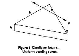
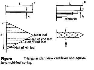
If it is desired to maintain uniform bending stresses over the length of the beam then the width of the cantilever needs to vary linearly with the location as illustrated in Figure i, (σb = M y/I = 12 F L y / b h3). The concept used in producing compact cantilever springs of uniform bending stress is to chop the triangular form illustrated in Figure i, into a number of strips and recombine them as illustrated in Figure ii. The multi-leaf spring shown and the single triangular section beam both have the same stress and deflection characteristics with the exceptions that the multi-leaf spring is subject to additional damping due to friction between the leaves and that the multi-leaf spring can carry a full load in only one direction due to the tendency for the leaves to separate. Leaf separation can be partially overcome by the provision of clips around the leaves.
|
|
|
The deflection of a triangular leaf spring is given by
![]()
where
F is force (N)
L is the length (m)
E is the Young’s modulus (N/m2)
I is the second moment of area (m4)
For a rectangular cross-section,
![]()
where b is width (m); and h is thickness (m).
The spring rate is given by

![]()
The corresponding bending stress (for cantilever, semi-elliptic and full-elliptic) is given by
![]()
For semi-elliptic beam the maximum deflection at the center is given by
![]()
For a full-elliptic beam the maximum deflection at the center is given by
![]()
* in the above equation the length b can be changed by nb’ where n is the number of leafs and b’ is the width of single leaf. The leaf width b’ is chosen from the available range of rolled products. It is desired that the following condition should hold
6 < b’/h < 10
6 < n < 14
The spring length can be determined using the equations for spring stiffness and stress to obtain

where
δ = is the total deflection (δst + δd)
- Effect of adding an extra full length number of leaves (ne) to the graduate length number of leaves (ng):

That means the extra leaves will have more stress than graduate ones.
![]()
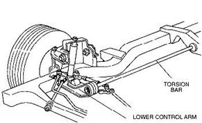
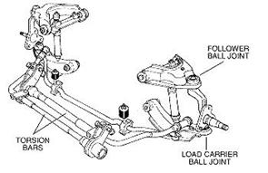
Torsion beam suspension (torsion bars)
Definition: A steel bar that is twisted to support the weight of the vehicle. Torsion bars are used in place of coil or leaf springs on some vehicles, and allow ride height to be adjusted to compensate for sage that occurs over time.
|
|
|
The bars are usually solid of circular cross section although hollow tubes and rectangular bars are used.
![]()
τall = 1000- 1050 MPa
The angle of twist and stiffness of a torsion bar are expressed as

The torsion-bar working length L (without spline ends) is determined by the θ equation. It is recommended to choose the diameters and lengths of spline ends depending on the torsion-bar diameter
dsp = (1.2 -1.3)d; and Lsp= (0.6-1.2)d
Car Weight Distribution
Static load
FE & FWD 66% Front (maximum braking 80%) 34% rear
Mid Engine 45% Front 55% rear
Sprung and Unsprung masses
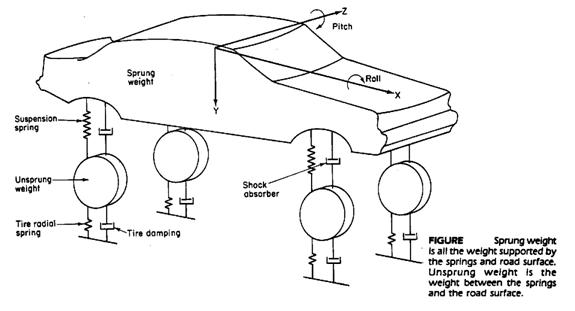
For passenger cars the ratio of unsprung mass to sprung masses is 1:10
Where the sprung mass is the car body and 2/3 of the suspension system, the unsprung mass is the vehicle axle and 1/3 of the suspension system.
Suspension Formulae

where b is the width of spring blade (m), L is the distance between the eyes of the spring when laden (m), t is the thickness of the blade (m), n is the number of blades, and E is the modulus of elasticity, which (modified to allow for internal friction) is 159 x 106 kN/m2.
For a torsion bar, the spring rate is given as the twisting moment per angular deflection. When a lever is added, this can be converted into a rate for the vertical deflection of the end of the lever.
Spring rate (torsion bar, for deflection at end of lever)

where G is the modulus of rigidity, which is 78.5 x 10⁶ kN/m2 in this case, d is the diameter of the torsion bar (m), l is the effective length of the torsion bar (m), i.e. half the length of the bar for an anti-roll bar, and e is the length of the lever (m).
Spring rate (coil spring)

where G is the modulus of rigidity, which is 81.5 x 10⁶ kN/m2 in this case, d is the wire diameter (m), n is the number of free coils, and D is the mean coil diameter (m). To find the number of free coils it is necessary to subtract the number of dead coils form the total number of coils. The dead coils are those that provide the abutment and so cannot be deflected, usually 1.5 to 2 coils.
Wheel rate:
The wheel rate is not the same as the spring rate, and depends on the effective leverage, or the separation of the springs relative to the track. Thus if the distance from the centre-line of the car to the spring on a beam axle is a, and the distance from the centre-line of the car to the centre-line of the wheel (i.e. half the track) is b, as shown in Figure 1 (a) then :
![]()

With independent suspension the formula is similar except that b is the length of the suspension arm and a is the distance form its pivot to the axis of the spring (Figure 1 (b)). With double-wishbone suspension the formula is modified to take into account the effects of the other whish bone on the geometry. The formula becomes:
Wheel rate CW = (CS × a2× c2)/(b2×d2) N/mm
where a, b, c, and d are as shown in Figure 2.


![]() kw
= ks
kw
= ks
Anti-roll bars
![]()

where
ke = equivalent rate
kw = wheel rate
ka = anti-roll bar rate measured at the wheel
Example:
The Porsche 928 is provided with a strong anti-roll at the front and a relatively weak one at the rear. The appropriate data are as follows:
Front Rear
Wheel rate (kN/m) 18.63 22.55
Anti-roll rate (at wheel) (kN/m) 83.4 10.2

Spring Design
![]()
where
k = wheel rate (N/mm)
m = mass of sprung mass on wheel (kg)
f = natural frequency (1.1 to 2.2 for comfort ride) = 1.5 cycle/sec
Spring rates and static deflection under 300 kg sprung mass
|
Frequency f (Hz) |
Spring rate (N/mm) |
Static deflection (mm) |
|
1.0 |
11.8 |
248 |
|
1.25 |
18.5 |
159 |
|
1.5 |
26.7 |
110 |
|
1.75 |
36.6 |
81 |
|
2.0 |
47.3 |
62 |
|
2.50 |
74.0 |
40 |