Brake Performance
Brakes are by far the most important mechanism (system) on any vehicle because the safety and lives of those riding in the vehicle depend on proper operation of the braking system. It has been estimated that the brakes on the average vehicle are applied 50,000 times a year.
“Brakes stop wheels-not vehicles”. This basic fact means that the best brakes in the world only stop rotation of the tire/wheel assembly. It is the friction between the tire and the pavement that accomplishes the stopping or slowing of the vehicle.
Brakes theory:
Brakes converts vehicle kinetic energy (KE) into heat energy (HE). Where the kinetic energy of the vehicle depends of the car mass and speed.
KE = ½ m v2
where:
m = mass of the car [kg]
v = velocity of the car [m/s]
Brake systems
Passenger-car brake systems can be classified according to the following criteria:
A- Design concepts, and
B- Operating principles.
A- Design concepts
Based on official regulations, the auto- motive braking equipment's functions can be divided into three brake systems:
- service-brake system (base brakes or foundation brakes)
- secondary-brake system, and
- parking-brake system.
Service-brake system
The service brakes (footbrake) can be employed to reduce the vehicle's speed, to maintain it at a constant level (for in- stance on a gradient) and to bring it to a halt. This is the system employed in the course of normal operation. It provides precisely-controlled, variable braking response at all four wheels.
Secondary-brake system
In the event that the service brakes fail, the secondary-brake system must be capable of assuming its functions, although it may generate only reduced braking force. The secondary (or auxiliary) brake system need not necessarily consist of a separate third system (supplementing the service and parking brakes) with its own control mechanism; it may also comprise the intact circuit in a dual-circuit service- brake layout or of a parking brake capable of graduated response.
Parking-brake system
The parking-brake (handbrake) system assumes the third braking function. It must be capable of maintaining the vehicle in a stationary state, even on gradients and in the absence of the driver. Safety considerations dictate that the parking-brake system features a continuous mechanical connection between the control mechanism and the wheel brake, e.g., linkage rods or a Bowden cable. The parking brake is actuated from the driver's seat, in most cases using a hand lever, in others via a pedal. This brake system is designed to provide graduated response. It operates on the wheels at one axle only.
B- Operating principles
Depending upon whether a brake system is operated completely, partially or not at all by
muscular energy, a distinction is drawn between:
- muscular-energy brake systems,
- power-assisted brake systems, and
- power-brake systems.
Muscular-energy brake systems
This type of system is installed in passenger cars and two-wheeled vehicles. The muscular force applied at the pedal or hand lever is transmitted to the brakes via a mechanical (linkage rods or Bowden cable) or hydraulic (master cylinder, wheel cylinders) relay system.
Power-assisted brake systems
The power-assisted (energy-assisted) brake system is found in passenger cars and light commercial vehicles. This type of unit employs a brake booster (servo unit) to supplement muscular force with energy generated by vacuum or hydraulic pressure. A hydraulic circuit then transmits this enhanced muscular force to the wheel cylinders.
Power-brake systems
The chief field of application for this non-muscular-energy brake system is in heavy commercial vehicles, but this type of system is also occasionally found in large passenger vehicles with integral antilock braking systems (ABS). With this system, the force used to operate the service brakes is entirely non-muscular.
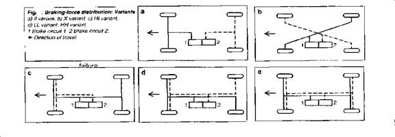
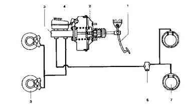
Brake-circuit configurations
Legal regulations define a dual-circuit transmission device as mandatory. Of the five options defined in DIN 74000, two versions (II and X) have become standard.
To ensure compliance with legal regulations governing secondary braking forces, front-heavy vehicles are equipped with a diagonal (X pattern) brake system; in this layout, each brake circuit controls one front wheel along with one rear wheel on the opposite side.
A system with separate circuits for the front and rear axles (II pattern) is particularly well-suited for use on rear-heavy vehicles and on medium-heavy and heavy-duty commercial vehicles. The remaining configurations (HT, LL, HH) are less satisfactory in terms of safety. As a result, the first two versions (II and X) are employed for virtually all applications.
 |
Brake-System Components
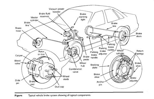 |
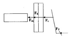
Brake Pedal: Increase foot pressure by simple mechanical leverage.
Booster (power-assisted brake system):
1- Vacuum booster: A relatively large metal chamber assembly installed between the firewall (bulkhead) and the master cylinder. Uses vacuum to create additional force to the master cylinder, making the stopping process easier on the driver
2- Hydraulic-booster: Brake booster that uses the pressure of hydraulic fluid to provide braking assistant.
A- Hydro-booster: Also referred to as Hydro-booster II, Hydra booster, or Bendix hydraulic booster. Hydraulic booster unit powered by the vehicle's power steering pump.
B- Power master: Sometimes called an electro hydraulic assist. Hydraulic power brake unit installed on some mid 1980's General Motor vehicles. Uses pressure supplied by an electrically driven hydraulic pump.
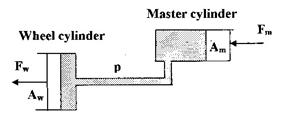
Master cylinder: Brake system device which stores fluid and provides the pressure to operate the other hydraulic components.
Brake lines: Hydraulic conduits made of steel that connect the stationary parts of the brake hydraulic system.
Hoses: Hydraulic conduits made of braided rubber that connects to the brake system parts which move in relation to each other.
Multi-circuit brake system: The multi-circuit brake system embodies a design in which forces are translated through two or more circuits.
Brake fluid: A special fluid compound used in hydraulic brake systems. It must meet exacting specifications, such as resistance to heating, freezing, and thickening.
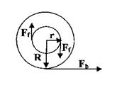
Wheel cylinder: Hydraulic device used in drum brakes to change hydraulic pressure from the master cylinder into mechanical force that applies the brake shoes against the rotating drum.
Disc brake caliper: Cast iron or aluminum cylinder and piston assembly used to receive, contain, and convert hydraulic pressure from the master cylinder to mechanical force against brake pads.
Disc Brake: A brake assembly that uses a hydraulic caliper to actuate brake pads against a metal rotor. Used for both front and rear brakes.
Drum brake: (Internal expanding brakes). It is a brake system that uses a wheel cylinder to force two brake shoes against a rotating drum. Used primarily as rear brakes.
Parking brake: A hand- or foot- operated brake which prevents vehicle movement while parked by actuating the rear brakes.
Parking brake cable: Stranded steel wire cable used to apply the parking brakes. Cable thickness is usually around 3/16 (4.76 mm).
Brake-pressure regulating valves:
1- Metering valve: Used to keep the front brakes from applying before the rear brakes.
2- Proportioning valve: Hydraulic valve used to equalize system pressure between the
front and rear brakes to prevent wheel lockup, installed in the rear brake line.
Anti-lock brake system (ABS): A computer-controlled system that is part of the base brake system. The system "cycles" the brakes on and off to prevent wheel lockup and skidding.
Power-brake system: Brake system in which the energy required to generate braking force is supplied by one or more devices producing a force completely independent of the driver's physical effort (compressed-air brake system).
Retarders (continuous or frictionless): like friction brakes, can be employed to reduce a vehicle's speed; however, they differ in being unsuitable for actually halting the vehicle. The retarder is suitable for use on extended gradients.
1- Exhaust brake (engine brake)
2- Hydrodynamic retarder
3- Electro dynamic retarder (Eddy-current brake)
Automatic brake system: The automatic brake system consists of all those elements which automatically apply braking force to a trailer's wheels in the event of intentional or accidental separation from the towing vehicle.
1- Trailer control valve
2- Inertia (overrun) brake system
3- Gravity brake system.
Brake operation:
Most vehicles built since the late 1920s use a brake on each wheel. To stop a wheel, the driver exerts a force on a brake pedal. The force on the brake pedal pressurizes brake fluid in a master cylinder. This hydraulic force (liquid under pressure) is transferred through steel lines to a wheel cylinder or caliper at each wheel. Hydraulic pressure to each wheel cylinder or caliper is used to force friction materials against the brake drum or rotor. The friction between the stationary friction material and the rotating drum or rotor (disk) causes the rotating part to slow and eventually stop. Since the wheels are attached to the drums or rotors, the wheels of the vehicles also stop.
Brake force analyses
 |
Mechanical Advantage (pedal lever ratio) {MA}:
 |
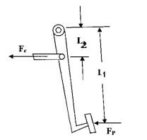 |
Booster Characteristics {B}:
 |
 |
Hydraulic Advantage {HA}:
 |
 |
Brake Factor {BF}:
 |
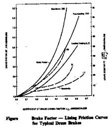 |
Braking Force {Fb}:
|
|
 |
Purpose of the brakes:
Brake systems discharge the followings:
- reduce vehicle speed, and bringing a moving vehicle to a halt,
- keeping the car speed a steady when moving down a gradient, and
- keeping a halted vehicle stationary.
*plus:
charging the battery, stabilizing the vehicle in the case of over and under-steering, preventing the wheel spin (TCS).
Brake system problems
a- Brake fade: Term given to gradual brake failure caused by brake overheating. Condition occurs when brake linings become so hot they can no longer create friction.
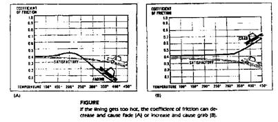 |
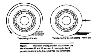
b-Wheel lockup: Wheel lockup happens when the wheels stop turning during stop, and sliding on the pavement. Braking under critical conditions:
Fb > f Ww
Where:
Fb is the braking force on the wheel,
f is the coefficient of adhesion between the tire and road, and
Ww is the weight on the wheel.
 |
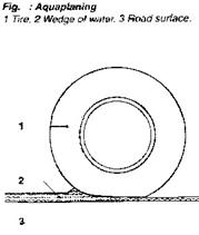
c- Aquaplaning:
Aquaplaning exercises a particularly dramatic influence on the contact between tire and road surface. This term refers to a state in which a layer of water separates the tire from the wet road surface. This phenomenon occurs when a wedge of water forms beneath the tire's contact patch, lifting it from the road. The tire starts to "swim".
| The tendency for aquaplaning to occur is influenced by: - the depth of the water on the road surface, - the vehicle speed, - the tread pattern, and - tire wear, as well as - the force with which the tire is being pressed against the road surface (tire load). Wide tires are particularly susceptible to aquaplaning. It is impossible to steer or brake an aquaplaning vehicle, as neither steering inputs nor braking forces can be transmitted to the road surface. |
 |
Dynamics of linear motion
(Braking force)
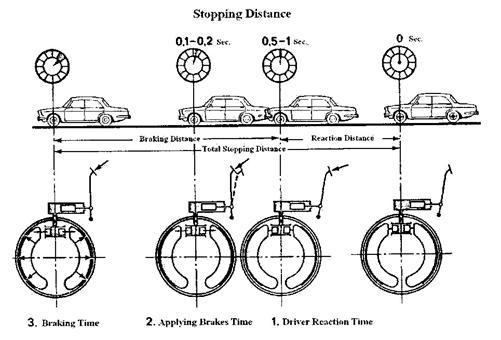
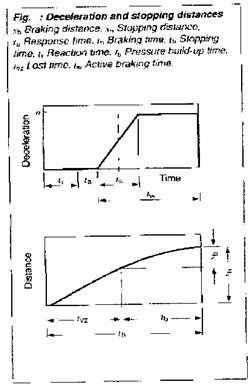
Stopping distance:
 |
|
|
Definitions when a hazard or obstacle is recognized and the point where the vehicle comes to a halt. It is the sum of the distance traveled during the reaction time tr, the brake system's initial response delay ta (at constant vehicle speed v) and the distance covered during the effective brake time ts. Alternatively, half of the pressure build-up period can be viewed as representing full deceleration. The periods in which no active retardation occurs are combined to form the cumulative response delay, or time loss tvs as seen in the figure.
tvs = tr+ ta + ts/2
and the total time th is the time loss plus the braking time tb
th = tvs + tb = tvs + v/a
and hence the total stopping time sh is
sh = v . tvs + v2/2a |
 |
Reaction time {tr}
The reaction time is the period that elapses between recognition of the hazard or obstacle, the driver's decision to apply the foot to the brake, and the time it takes for the foot contact the brake pedal. The reaction time is not a fixed constant; depending upon the individual deriver and various environmental variables, it can rage from 0.3 to 1.7 seconds
Brake response and pressure build-up times
The brake response and pressure build up times t, and t, are defined by the brake system's
control and transmission devices as well as by the instantaneous condition of the brakes
themselves (i.e. wet brake rotors or discs).This time can rage from 0.36 to 0.54 seconds (ta + ts/2). The response and pressure build-up times are longer if the brake system is in poor condition.
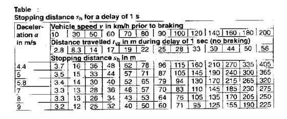
A stopping response delay of 1 s results in the stopping distances indicates in the table below.
 |
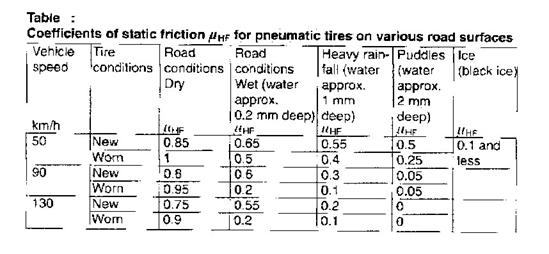
Surface adhesion
Static coefficient of friction:
The static coefficient of friction (tire-road interface friction coefficient) is defined by such factors as vehicle speed, tire condition and the state of the road surface. The figures in the table apply to concrete and tar macadam surfaces in good condition. The coefficient of sliding friction (with wheel locked) is generally lower than the coefficient of static friction.
 |
Anti-lock brake system
Problems arise from the wheel lockup:
A- If the front wheels lockup first, there will be a loss of directional control.
B- If the rear wheels lockup first, there will be a loss directional stability.
 |
ABS components:
1- Wheel speed sensor: Permanent magnet sensor used to detect wheel speed by monitoring the movement of the wheel.
2- Electronic Brake Control Module (EBCM) OR (ECU): A computer that controls the operation of the ABS system.
3- Hydraulic actuator: Anti-lock brake system consisting of solenoid valves, a hydraulic pump, an accumulator, and various tubing connections and electrical connectors.
4- ABS warning light: Amber indicator lamp mounted in the instrument cluster, illuminates when there is a problem with the anti-lock brake system.
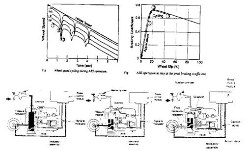
Theory of operation:
When the brakes are first applied, wheel speeds diminish more or less in accordance with the vehicle speed in region 1 in the plot. If the brakes are applied to a high level, or the road is slippery, the speed of one or more wheels begin to drop rapidly (point 2), indicating. that the tire has gone through the peak of the m-slip curve and is heading toward lockup. At this point the ABS intervenes and releases the brakes on those wheels before lockup occurs (point 3).
Once the wheel speed picks up again the brakes are reapplied. The objective of the ABS is to keep each tire on the vehicle operating near the peak of the m-slip curve for that tire, as shown in the figure.
 |