Heavy-Duty Vehicle Air Brake System
Theory of brake operation
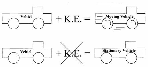
Vehicle in motion posses a kinetic energy (K.E.), this kinetic energy increases as the vehicle mass and velocity increases. Where the kinetic energy is:
|
|
![]()
where:
K.E. is the kinetic energy [J, N m]
m is the mass of the vehicle [kg]
v is the vehicle speed [m/s]
To stop the car we have to get red of the kinetic energy (K.E.) but; Energy cannot be destroyed, it is always conserved. Then, the only way to get red of the kinetic energy is to transfer it to another form of energy.
The theory of brakes is to convert the kinetic energy of a moving vehicle to thermal (heat) energy using the friction.
The advantages if air brake system
• No cost
As an operating medium, air costs nothing and is always available.
• No leaking problem
Very minor leaks are not critical (the compressor continually supplies more air pressure).
• No pressure drop and faster air transmit. Air brake lines have large inside diameter. (Hydraulic brakes are not very suitable for long wheelbase trucks).
• Suitable for connection with trailer.
• Source of energy operates various equipment on the vehicle (Door control etc.).
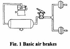
Basic installation of air brakes
There is no direct connection in any mechanical or hydraulic sense between the brake treadle (leaver worked by the foot, pedal) and the wheel brake chambers, although the driver is provided with a certain degree of feel related to system air pressure during braking.
The operation of a basic single-circuit air brakes system Fig. 1 is such that when the brake treadle is depressed one of two related control valve is opened, so that air under pressure from the reservoir can press through the control valve and into each wheel brake-actuating chamber. Here the compressed air acts against a diaphragm, its resulting movement being transmitted via a push-rod to either the operating lever of the brake camshaft, or the wedge of a braked expander unit, which forces the shoes against the brake drum.
As the brake treadle is released, the previously mentioned control valve closes and the other one is opened, thereby allowing the air under pressure in the brake chambers to be exhausted to the atmosphere and the shoe return springs release the brakes.
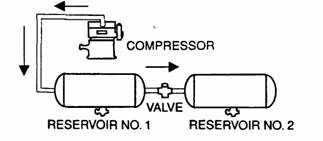
This energy in the compressed air can be used to do the work.
The compressed air may be defined, as air that forced into a smaller space than it would ordinarily occupy into its free atmospheric state. If we connect to reservoirs together, air flows from high-pressure reservoir to the low-pressure reservoir until the pressure equalizes in the two reservoirs.
|
|
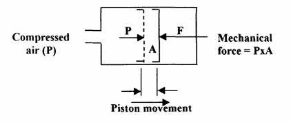
When compressed air is supplied on one side of a moveable piston or flexible diaphragm in a sealed chamber, the air pressure cause the piston or flexible diaphragm to move until an equal force is supplied to the other side of the piston.
|
|
The Air Operated Power Brake System
General background
In 1868 the American engineer George Westinghouse first patented his invention for an automatic compressed air brake for railway train.
With a diesel engine either a vacuum pump was necessary, or it could be just as economical to fit a pressure pump for compressed air braking, with its greater power. Both railway and heavy-vehicle engineers have therefore considered preferable to utilize a source of compressed air, generally at 700 kN/mm2 or more.
The higher operating pressures that are made possible with compressed air brakes allow a reduction is size of the system components, a companied by quicker application and release characteristics.
The need for an air operated power brake system
The medium and heavy commercial vehicles has bigger mass than privet cars, which leads to an increase in the kinetic energy. Truck brakes may be defined as mechanical devices that retard the motion of the truck by friction, and during this process the energy of motion changed into heat energy. The truck brakes must absorb and dissipate this heat.
Great forces are required to stop a truck especially from high speed. As the size and weight of road vehicles increase, the force exerted by the driver’s foot becomes insufficient. That led to the use of compressed air as a medium for energy supply and as a transmission device, the advantage of air brakes are:
• More powerful
-Air pressure (7-8 bar)
- vacuum booster pressure (- 0.9 bar) {diesel engine (no vacuum source)}
- hydraulic booster pressure (50- 60 bar .... line pressure 100 bar). Because of this high pressures, a small diameter servo cylinder are used (leak problems).
* Operate at a pressure of only one-tenth of an equivalent hydraulic source, but for large vehicles where there is more space, there is not real problem as much larger diameter cylinders can be used.
Truck Class
|
Truck |
Class |
GVW* (pound) |
GVW (kg) |
|
Light-duty |
1 |
Up to 6000 |
Up to 2667 |
|
2 |
6000-10,000 |
2668-4444 |
|
|
3 |
10,001-14,000 |
4445-6222 |
|
|
Medium-duty |
4 |
14,001-16,000 |
6223-7111 |
|
5 |
16,001-19,500 |
7112-8667 |
|
|
6 |
19,501-26,000 |
8668-11,556 |
|
|
Heavy-duty |
7 |
26,001-33,000 |
11,557-14,667 |
|
8 |
33,000 and over |
14,668 and over |
* Gross Vehicle Weight (GVW)
Compressed air
The normal atmospheric pressure around us is approximately 14.7 psi (101.28 kPa) depending on altitude, humidity, temperature, and other factor. When we discussing compressed air we ignore the 14.7 psi (101.28 kPa) atmospheric pressure, and consider the atmosphere to contain free air under no pressure (air pressure gauges read zero when connected only to atmospheric pressure).
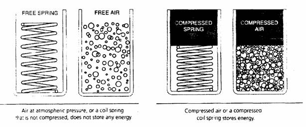
Air in its free or compressed state may be compressed state may be compared to a coil spring. When coil spring is not compressed, it does not store any energy. Similarly, air in its atmospheric or free state does not store any energy. When a coil spring is compressed it stores energy, and compressed air also stores a specific amount of energy.
|
|
|
|
Air brakes components
• Compression and storage (compressed air supply)
• System control (pressure regulators, valves)
• System actuating (service-brake system, parking-brake system)
• Trailer control
• Air compressed operation and equipment (pneumatic suspension, door control).
Balancing brake system
Balancing brake system is the system in which equal air pressure reaches each brake chamber at the same time. If an air brake system does not have proper balance, one wheel may lock up prematurely during brake application. This wheel lockup may cause the tractor and trailer to go into uncontrollable jackknife situation.
o You must never change brake system components (tubing, hose, or fittings) with different size or length as original.
o Brake tubing must never be bent or restricted.
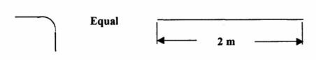
o Straight fittings must never be replaced with elbows. (Air flow time through an elbow is the same as air flow through the same size of tubing 2 m long).
|
|
o Contamination with moisture, ice, oil in the brake line, valves and components may interfere with brake system balance.
o Slack adjustment is very important to obtain proper brake balance. Some slack adjusters are self-adjusting, but other bust be manually adjusted.
Compressors
o The air delivery temperature should not exceed 220 °C.
o The total cylinder swept volume capacity needed for an air brake system with possibly auxiliary equipment for light, medium and heavy commercial vehicle ranges from about 150 cm to 500 cm which provided by either single or twin cylinder reciprocating compressor.
o The maximum crankshaft speed of these compressors is anything from 1500 to 3000 rev/mm depending upon maximum air pressure and application.
o The maximum air pressure a compressor can discharge continuously varies from 7 to 11 bar. A more typical maximum pressure value would be 9 bar.
o The quantity of air that can be delivered at maximum speed by these compressors ranges from 150 L/min to 500 L/min for a small to large size compressor. This corresponds to a power loss of something like 1.5 kW to 6 kW respectively.
o Governor cut-out pressure is 120 psi (861.87 kPa), and a typical cut-in pressure is 105 psi (723.97 kPa), must not be more 25 psi (172.37 kPa) below the cut-out pressure.
o Reservoirs are actually designed to withstand 500 psi (3,447.5 kPa).
o Reservoirs are supplied in various lengths and different diameters, from 3.5 to 14 in (8.89 to 35.56 cm).
o Reservoir volumes vary from 100 to 7,600 Cu. in. (1638.7 to 124,541.2 cc).