|
|

Engine types and classifications
There are many ways to classify an engine, even though the fundamental parts (block, pistons, crankshaft, camshaft are basically the same. These design differences, however, can greatly affect how the engine performs and how it is served.
Modern automotive engines are normally classified by:
1. Number of cylinders and engine swept volume (4,6,8,12,3,5,2), (cc, L)
2. Arrangement of cylinders (In-line, V-type, Slant, Horizontally).
3. Type of fuel burned (Gasoline, Diesel, LPG,…).
4. Ignition classifications (Spark, Compression ignition).
5. Method of fuel entry into engine(Carburetor, Injection).
6. Method of air-fuel mixture entry into engine (Normal aspiration , Turbo and Supercharging).
7. Cooling system type (Liquid, Air cooling systems).
8. Number of valves per cylinder. (2, 4-Valve combustion chamber).
9. Cam shaft location (OHC, DOHC).
10. Number of stroke per cycle. (2, 4-storke engine).
Engine position
Front Engine:
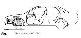
Apart from tradition there are a number of reasons for sitting the engine at the front of a car as shown in the figure.
o The large mass of an engine at the front of the car gives the driver protection in the event of a head-on collision,
o Engine cooling is simpler to arrange,
o The cornering ability of the vehicle is normally better if the weight is concentrated at the front.
Rear Engine:
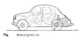
By placing the engine at the rear of the vehicle it can be made as a unit that incorporates the clutch, gearbox and final drive assembly. With such an arrangement it is necessary to use some form of independent rear suspension. Most rear-engine layouts have been confined to comparatively small cars, because the heavy engine at the rear have adverse effect on the “handling” of the car by making it ‘tail-heavy’. Also it takes up a good deal of space that would be used on a front-engined car for carrying luggage. Most of space vacated by the engine at the front end can be used for luggage, but this space is usually less than that available at the rear.
Central and mid-engine:
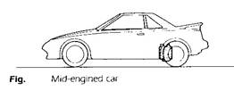
These engine situations generally apply to sports cars because the engine sitting gives a load distribution that achieves both good handling and maximum traction from the driving wheels. These advantages, whilst of great importance for special cars, are outweighed in the case of everyday cars by the fact that the engine takes up space that would normally be occupied by passengers.
General layout of cars
Many different layouts are used with each arrangement offering specific advantages. Variation occurs in the location of the engine and the driving arrangement, i.e. the number and position of the driving wheels.
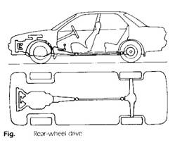
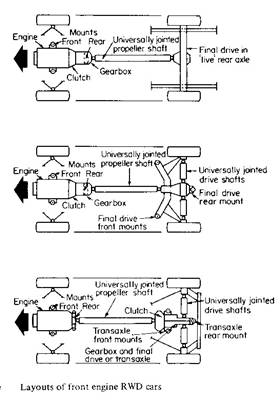
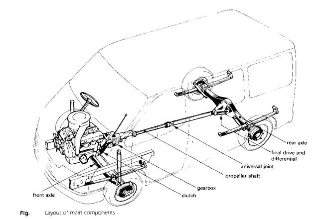
Front engine and Rear-wheel drive (RWD):
|
The traditional layout shown in the figure has the engine situated with its output shaft set longitudinally. In this arrangement the rear wheels act as the driving wheels and the front wheels swivel to allow the vehicle to be steered. In the past rear wheel drive was a natural choice because of the difficulty of transmitting a drive to a wheel that had to swivel for steering purposes.
Spacing out the main components in this layout makes each unit accessible but a drawback is the intrusion of the transmission components into the passenger compartment.
Using the rear wheels to propel the car utilizes the load transfer that takes place from the front to rear of vehicle when the car is climbing a hill or accelerating. Good traction is obtained but when the wheels lose adhesion, the driving wheels move the rear of the car sideways.
|
|
|
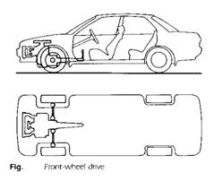
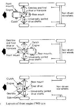
Front engine and Front-wheel drive (FWD):
|
The compactness of the layout shown in the figure has made it very popular for use on cars. The advantage associated with the engine being placed across the vehicle, i.e. mounted transversely, and has spread the use of front-wheel drive to many cars. Accommodating all the main components under the bonnet (hood) in one compartment give maximum space within the car for the occupants; also absence of floor bulges and tunnel provides more room for the rear passengers. Transverse mounting of the engine simplifies the transmission, because the output shafts from the engine and gearbox move in a similar direction to the wheels. This avoids the need for a bevel-type final drive; instead a simple reduction gear, incorporating a differential, transits the power by short drive shafts to the road wheels. One criticism of front-wheel drive is that the driving wheels have less grip on the road when the vehicle is accelerating and hill-climbing. Although this characteristic can be partly corrected by placing the engine well forward to increase the load on the driving wheels, the car is then liable to become ‘nose-heavy’. The effect of this is to make the steering of the car more arduous. In cases where the driver’s steering effort is considered excessive, the car is often fitted with power-assisted steering.
|
|
|
Using the front wheels for steering allows the driving force to act in the same direction as wheel is pointing. This feature, together with the fact that the vehicle is being ‘dragged’ behind the front driving wheels, improves vehicle handling especially in slippery conditions.
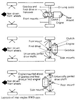
Rear Engine and rear wheel drive (RWD):
|
In the now less popular rear engined car, the engine is mounted either fore-and aft behind t transaxle or transversely behind the gearbox and final drive unit.
One advantage attributed to a rear-engined layout is that it increases the load on the rear driving wheels, giving them better grip of the road.
|
|
|
Four-wheel drive (4x4) and (AWD):
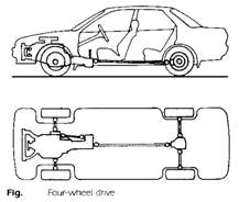
This arrangement, shown in the figure, is safer because it distributes the drive to all four wheels. The sharing of the load between the four wheels during acceleration reduces the risks of wheel spin. Also the positive drive to each wheel during braking minimizes the possibility of wheel lock-up.
A further advantage of this layout is shown when the vehicle is driven on slippery surfaces such as snow and mud.
The 4x4 (4WD) gives the driver the choice of operating in either 2WD or 4WD through the use of a shift lever or shift button. The AWD system operates in continuous 4WD.
Power Train
The Clutch
A clutch is a device for connecting or disconnecting two shafts. It may be a dog clutch, where the engagement is positive through projections on one member mating with corresponding indentions on the other, or a friction clutch, where the torque is transmitted through friction surfaces which allow a progressive engagement as they are brought together.
A friction cultch is necessary between the engine and gearbox to disengage and permits a smooth and gradual re-engagement of the drive. When engaged, the clutch must transmit the maximum engine torque without slipping, and when disengaged for gear changing it must not exert a drag on the idle member.
The internal combustion engine must revolve at a reasonable speed to develop sufficient torque to move the vehicle from rest and, when starting this engine torque must be smoothly and gradually conveyed to the gearbox without shock at the transmission.
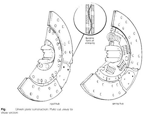
The single-plate dry clutch:
 The driving members of the clutch consist of the
flywheel and the pressure plate both being of cast iron. The pressure plate is
caused to revolve with the flywheel by three or four sets of tempered-steel
straps arranged tangentially between the pressure plate and the cover, whilst
their flexibility in bending allows for the axial movement of the pressure
plate. Alternatively projections on the pressure plate engage and slide in
slots in the cover.
The driving members of the clutch consist of the
flywheel and the pressure plate both being of cast iron. The pressure plate is
caused to revolve with the flywheel by three or four sets of tempered-steel
straps arranged tangentially between the pressure plate and the cover, whilst
their flexibility in bending allows for the axial movement of the pressure
plate. Alternatively projections on the pressure plate engage and slide in
slots in the cover.
A series of springs located between the cover and the pressure plate force the latter towards the flywheel face, trapping the friction-lined driven plate or clutch disc between these two surfaces.
The clutch shaft supported in the gearbox by a journal bearing and in the flywheel by a spigot bearing is splinded to fit the hub of the clutch disc and transmits the torque from the driven disc to the gearbox.
The driven plate may incorporate a spring-cushioning hub to reduce shock loading during engagement and absorb tensional vibrations. The hub springs can be arranged to have a progressive action by varying rates or end clearances, and some form of friction damping can be provided between the hub and the plate to absorb the tensional energy.
The riveted-on linings are of bounded asbestos and have a coefficient of friction on the cast-iron surfaces of 0.3-0.4. The spring-steel leaves carrying the linings may be arranged to slightly separate the two rings of material when free, so as to give a smooth action as they pressed together during engagement. Slotting the plate eliminates heat distortion.
|
|
 |
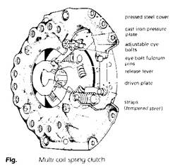
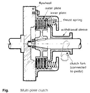
The multi-plate clutch
The torque transmitted by a plate-type clutch depends on four factors, the number of friction surfaces (n), total spring thrust (normal force) (Fn), Coefficient of friction (m),and the mean radius (rm). The formula to calculate the torque capacity is
T = n m Fn rm
Where
Rm = (ro+ ri)/2
ro is the outer radius of the friction material,
ri is the inner radius of the friction material.
There are cases where the springs thrust, friction, or clutch radius must be restricted, so in theses cases the number of plates has to be increased to ensure that the maximum torque can be transmitted without slip. A clutch having more than one driven plate is called a multi-plate clutch.
This type of clutch was widely used on cars on the past but a modern use of a multi-plate type is in automatic gearboxes. This type of gearbox needs a number of clutches to hold the various gear elements, and since the clutch diameter in this application is limited, a multi-plate clutch is commonly used. The clutch may be either wet or dry. The clutch employed in the automatic gearbox is generally of the wet type, and is operated by a piston controlled by hydraulic pressure.
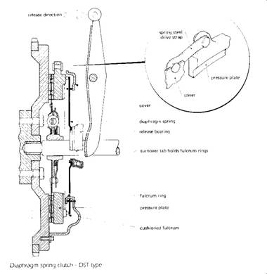
Diaphragm-spring clutch:
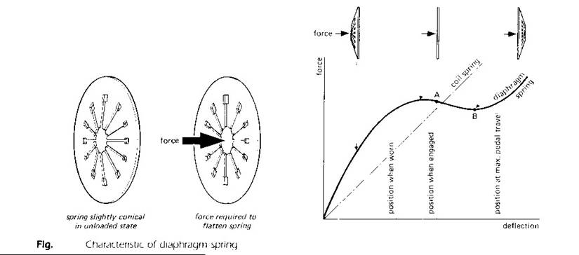
In the diaphragm-spring clutch the coil springs and the releases livers are replaced by a Belleville-type spring-steel ring slightly coned when free, flat when providing the clamping load, and coned in the reverse direction during withdrawal.
The diaphragm spring pivots on two fulcrum rings held by shouldered rivets to the clutch cover. Alternatively, the rings may be secured by integral tongues on the cover pressing, which are clenched over during manufacturing assembly. The outer rim of the diaphragm spring is retained in the pressure plate and its inward-pointing tapered fingers are acted upon by the release bearing.
The force produced by a diaphragm spring is not directly proportional to the deflection, i.e. it does not follow Hook’s law. Consequently clutch-pedal forces can be reduced whilst the clamping-spring pressure remains almost constant throughout the life of the linings. Other advantages of the diaphragm-spring clutch are a simplified construction, a more even circumferential clamping force, an independence of centrifugal force (unlike coil springs), and a more accurate balance.
Example:
An engine develop 146 N.m torque which is transmitted through a single plate clutch of mean diameter 250 mm. If the coefficient of friction between the surfaces is 0.3, calculate the minimum total clutch-spring force required to transmit this torque.
Let Fn be the minimum total spring force. This is the normal force between the surfaces. The friction force for the two sides of a single-plate clutch = 2 m Fn [N], hence
Tcl = 2 m Fn r [N.m]
Where: r = mean radius [m], then
Fn = Tcl /(2 m r ) [N]
= 146/ (2 x 0.3 x 0.125)
= 1946.7 [N]
The minimum total clutch-spring force required to transmit the torque without slip will be 1946.7 N.
The clutch torque actually designed with a higher value than the engine maximum torque.
Tcl = fd Te mas
Where:
Te max = maximum engine torque.
fd = design factor (safety factor) = 1.2- 1.6
the design factor is to accommodate for the; increase in engine torque, wear in the friction material (decrease in normal force), decrease in coefficient of friction.
Direct Shift Gearbox (DSG):
The (DSG) is a double clutch, which consists of two
wet plate-type clutches with hydraulically regulated contact pressure. One of
the two clutches engages the odd-numbered, the other the even-numbered gears.
This principle enables gear shifts to be made without interrupting the power
flow and keeps the shift times extremely short. While the first clutch is
transmitting the power, the second clutch is ready to engage the next gear,
which is preselected. When the driver makes the gear shift, the first clutch is
released and the second engages, so that the gear shift takes place in a fraction
of a second.
The driver can operate the DSG manually or allow changes to take place
automatically. In the automatic mode there is a choice between the
well-balanced, comfortable standard shift settings and a program with
greater sports emphasis. Manual shifts are made either at the gear
lever or at shift paddles behind the steering wheel.